logo
Products
PRODUCTS DETAILS
Home > Products >
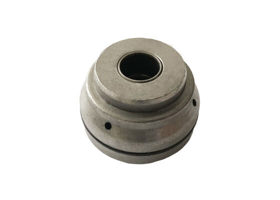
Powder Metallurgy Shock Absorber Rod Guide for Precise Piston Rod Alignment

Powder Metallurgy Shock Absorber Rod Guide for Precise Piston Rod Alignment

MOQ: 1000pcs
Price: negotiation
Standard Packaging: Standard exporting package
Delivery Period: 30 working days for new samples
Payment Method: T/T
Supply Capacity: 50,000pcs per month
Detail Information
Place of Origin
China
Brand Name
XIAYI
Certification
IATF16949:2016
Model Number
OEM sinter parts
Product Name:
Sinter Guider
Material:
Fe - C - Cu
Press:
80 - 150T
Service:
OEM
Application:
Shock Absorber
Treatment:
Steam
Hardness:
HRB70-90
Molds Time:
25 Days
Highlight:

Powder Metallurgy Shock Absorber Guide

,

Precise Piston Rod Alignment Guide

,

Shock Absorber Rod Guide

Product Description
1. Product Overview

A shock absorber rod guide is an important internal component of a hydraulic damper. It is generally installed at the upper section of the damper body, where the piston rod passes through the housing. Its main functions include guiding the piston rod, providing radial support, and accommodating related assembly components.

During compression and rebound cycles, the piston rod repeatedly moves along its designed axis. The guide bore dimensions, concentricity, material hardness, and surface condition influence rod-to-guide fit, contact wear, and the operating conditions of the sealing system.

XIAYI manufactures powder metallurgy rod guides for automotive and motorcycle shock absorbers. Using an iron-based Fe-C-Cu material system, the products can be evaluated according to different damper designs, dimensional requirements, and finishing specifications.

The manufacturing route may include powder compaction, sintering, sizing, precision machining, and surface treatment. Critical dimensions such as the guide bore and outer diameter are controlled according to customer drawings and assembly requirements.

Different configurations are available for automotive and motorcycle suspension applications, with OEM development support based on technical drawings or physical samples.

2. Product Structure and Technical Features 2.1 Precision Piston Rod Guidance

The primary function of the rod guide is to maintain the piston rod along its intended movement axis inside the damper.

The guide bore size and clearance between the guide and piston rod must be determined according to the mating design.

Proper dimensional matching helps control rod deflection, reduces the risk of abnormal contact and localized wear, and provides a suitable assembly interface for the oil seal and other components.

2.2 Fe-C-Cu Powder Metallurgy Material

XIAYI offers rod guide products using an iron-based Fe-C-Cu powder metallurgy material system.

Material density and hardness are important considerations when evaluating load support, wear behavior, and machining suitability.

Material specifications and manufacturing processes should be confirmed for each model rather than applying the properties of one reference product to every rod guide.

2.3 Steam Treatment and Surface Condition

Steam treatment is one of the available finishing processes for iron-based powder metallurgy components. It can form an oxide layer on the component surface.

For products using this process, treatment duration, oxide-layer thickness, and surface quality can be specified and reviewed according to technical requirements.

The resulting surface condition must also be compatible with the intended operating environment and assembly design.

2.4 Guide Bore and Oil Seal Interface

The rod guide must fit the piston rod and may also form an assembly interface with the oil seal, bushing, and damper housing.

Critical dimensions may include:

Guide bore diameter and roundness.

Outer diameter and installation fit.

Concentricity between the bore and outer diameter.

End-face dimensions and perpendicularity requirements.

Chamfers and assembly lead-in geometry.

Specific tolerances should be defined by the approved drawing for each damper design rather than relying on a universal dimensional standard.

2.5 Optional DU Bushing Assembly

Certain rod guide designs can be evaluated with DU sliding bushings or other bearing components.

The use of a bushing, its material, and its installation configuration should be determined according to the guide structure and piston rod operating conditions.

3. Shock Absorber Rod Guide Technical Specifications

The following specifications are reference values identified in existing product information. They are intended for initial technical communication and should be matched to the relevant model.

Parameter

Reference Data

Technical Notes

Product

Shock Absorber Rod Guide

Piston rod guiding component

Manufacturing process

Powder Metallurgy

Powder compaction and sintering

Material system

Fe-C-Cu

Iron-carbon-copper powder metallurgy

Reference density

6.4–6.8 g/cm³

Recorded in existing product specifications

Reference hardness

HRB 70–90

Recorded for the reference 30.5 mm model

Reference model

30.5 mm

Model identifier; not necessarily the outside diameter

Reference net weight

202 g

For the corresponding reference model

Surface treatment

Steam Treatment

Applied according to product requirements

Reference treatment time

2 hours

Recorded process parameter

Oxide-layer thickness

0.004–0.005 mm

Reference value for steam-treated products; confirm by model

Guide bore diameter

According to drawing

Matched to the piston rod

Outside diameter

According to drawing

Matched to the damper housing or installation structure

Concentricity and roundness

According to customer drawing

Defined by assembly and guiding requirements

Inspection items

Dimensions, hardness, density, surface condition, and specified material properties

Inspection plan depends on the order requirements

Applications

Automotive and motorcycle shock absorbers

Final compatibility depends on the component design

4. Manufacturing Process and Quality Control

The manufacturing route for a powder metallurgy shock absorber rod guide is determined by component geometry, material requirements, and dimensional tolerances.

A typical XIAYI production route may include:

Process Stage

Manufacturing Operation

Main Control Objective

1. Powder Blending

Material proportioning and powder mixing

Composition and mixing uniformity

2. Powder Compaction

Forming in a dedicated die

Green part geometry and forming quality

3. Sintering

Sintering under specified conditions

Material bonding and structural properties

4. Sizing and Calibration

Calibrating critical dimensions

Dimensional and geometric accuracy

5. Deburring

Removing burrs at specified locations

Bore and edge condition

6. Precision Machining

Machining required mating features

Bore, OD, and critical dimensions

7. Steam Treatment

Surface treatment when specified

Oxide layer and surface condition

8. Final Inspection

Dimensional and specified performance checks

Compliance with drawing and acceptance criteria

Key Inspection Items

Guide Bore Inspection: Verify bore dimensions, roundness, and fit with the mating piston rod.

Geometric Inspection: Check the outside diameter, end faces, concentricity, and other drawing-defined features.

Hardness and Density Testing: Verify the relevant material properties against the approved specification.

Surface Treatment Inspection: Review the steam-treated surface and oxide-layer condition where required.

Visual Inspection: Check for cracks, edge chipping, abnormal burrs, and other visible defects that may affect assembly.

Inspection methods, sampling rates, and acceptance criteria can be defined according to the customer's technical agreement.

5. Typical Applications

Application

Main Technical Requirements

Passenger Car Shock Absorbers

Piston rod guidance, radial support, and oil seal interface

Commercial Vehicle Shock Absorbers

Material and dimensional requirements based on rod loading and guide structure

Motorcycle Front Forks

Compact geometry, guide bore dimensions, and assembly space

Motorcycle Rear Shock Absorbers

Piston rod guidance and compatibility with sliding components

Construction Machinery Dampers

Material and process evaluation based on loading and operating conditions

OEM Shock Absorber Programs

Product development based on drawings, samples, and technical specifications

6. Customization and Quotation Requirements

To evaluate the manufacturing route and prepare an accurate quotation, please provide:

2D drawing or 3D model of the rod guide.

Mating piston rod diameter and surface treatment information.

Required guide bore, outside diameter, thickness, and critical tolerances.

Material grade, density, and hardness requirements.

Steam treatment or DU bushing assembly requirements, if applicable.

Expected order quantity, annual demand, and quality acceptance criteria.

XIAYI can review component geometry, material specifications, and machining requirements based on customer drawings and operating conditions, supporting OEM development and volume supply for automotive and motorcycle shock absorber rod guides.

7. Frequently Asked Questions Q1: What is the main function of a shock absorber rod guide?

A rod guide supports and guides the piston rod during movement, helps maintain its intended alignment inside the damper, and provides an assembly interface for the oil seal and related components.

Q2: What materials are used for XIAYI shock absorber rod guides?

XIAYI offers rod guides using an iron-based Fe-C-Cu powder metallurgy material system. The exact specification should be confirmed for the selected model and technical requirements.

Q3: What does steam treatment do for a powder metallurgy rod guide?

Steam treatment can form an oxide layer on the surface of iron-based powder metallurgy parts. The treatment duration, oxide-layer thickness, and suitability should be confirmed according to the actual process and product model.

Q4: Can a rod guide be supplied with a DU bushing?

Certain rod guide designs can be evaluated with a DU bushing assembly. The final configuration depends on guide geometry, bushing dimensions, and piston rod fit requirements.

Q5: Can XIAYI manufacture rod guides according to customer drawings?

Yes. XIAYI can review customer drawings, samples, and technical requirements, with particular attention to bore dimensions, outside diameter, concentricity, material, and surface treatment.

Products
PRODUCTS DETAILS
Powder Metallurgy Shock Absorber Rod Guide for Precise Piston Rod Alignment
MOQ: 1000pcs
Price: negotiation
Standard Packaging: Standard exporting package
Delivery Period: 30 working days for new samples
Payment Method: T/T
Supply Capacity: 50,000pcs per month
Detail Information
Place of Origin
China
Brand Name
XIAYI
Certification
IATF16949:2016
Model Number
OEM sinter parts
Product Name:
Sinter Guider
Material:
Fe - C - Cu
Press:
80 - 150T
Service:
OEM
Application:
Shock Absorber
Treatment:
Steam
Hardness:
HRB70-90
Molds Time:
25 Days
Minimum Order Quantity:
1000pcs
Price:
negotiation
Packaging Details:
Standard exporting package
Delivery Time:
30 working days for new samples
Payment Terms:
T/T
Supply Ability:
50,000pcs per month
Highlight

Powder Metallurgy Shock Absorber Guide

,

Precise Piston Rod Alignment Guide

,

Shock Absorber Rod Guide

Product Description
1. Product Overview

A shock absorber rod guide is an important internal component of a hydraulic damper. It is generally installed at the upper section of the damper body, where the piston rod passes through the housing. Its main functions include guiding the piston rod, providing radial support, and accommodating related assembly components.

During compression and rebound cycles, the piston rod repeatedly moves along its designed axis. The guide bore dimensions, concentricity, material hardness, and surface condition influence rod-to-guide fit, contact wear, and the operating conditions of the sealing system.

XIAYI manufactures powder metallurgy rod guides for automotive and motorcycle shock absorbers. Using an iron-based Fe-C-Cu material system, the products can be evaluated according to different damper designs, dimensional requirements, and finishing specifications.

The manufacturing route may include powder compaction, sintering, sizing, precision machining, and surface treatment. Critical dimensions such as the guide bore and outer diameter are controlled according to customer drawings and assembly requirements.

Different configurations are available for automotive and motorcycle suspension applications, with OEM development support based on technical drawings or physical samples.

2. Product Structure and Technical Features 2.1 Precision Piston Rod Guidance

The primary function of the rod guide is to maintain the piston rod along its intended movement axis inside the damper.

The guide bore size and clearance between the guide and piston rod must be determined according to the mating design.

Proper dimensional matching helps control rod deflection, reduces the risk of abnormal contact and localized wear, and provides a suitable assembly interface for the oil seal and other components.

2.2 Fe-C-Cu Powder Metallurgy Material

XIAYI offers rod guide products using an iron-based Fe-C-Cu powder metallurgy material system.

Material density and hardness are important considerations when evaluating load support, wear behavior, and machining suitability.

Material specifications and manufacturing processes should be confirmed for each model rather than applying the properties of one reference product to every rod guide.

2.3 Steam Treatment and Surface Condition

Steam treatment is one of the available finishing processes for iron-based powder metallurgy components. It can form an oxide layer on the component surface.

For products using this process, treatment duration, oxide-layer thickness, and surface quality can be specified and reviewed according to technical requirements.

The resulting surface condition must also be compatible with the intended operating environment and assembly design.

2.4 Guide Bore and Oil Seal Interface

The rod guide must fit the piston rod and may also form an assembly interface with the oil seal, bushing, and damper housing.

Critical dimensions may include:

Guide bore diameter and roundness.

Outer diameter and installation fit.

Concentricity between the bore and outer diameter.

End-face dimensions and perpendicularity requirements.

Chamfers and assembly lead-in geometry.

Specific tolerances should be defined by the approved drawing for each damper design rather than relying on a universal dimensional standard.

2.5 Optional DU Bushing Assembly

Certain rod guide designs can be evaluated with DU sliding bushings or other bearing components.

The use of a bushing, its material, and its installation configuration should be determined according to the guide structure and piston rod operating conditions.

3. Shock Absorber Rod Guide Technical Specifications

The following specifications are reference values identified in existing product information. They are intended for initial technical communication and should be matched to the relevant model.

Parameter

Reference Data

Technical Notes

Product

Shock Absorber Rod Guide

Piston rod guiding component

Manufacturing process

Powder Metallurgy

Powder compaction and sintering

Material system

Fe-C-Cu

Iron-carbon-copper powder metallurgy

Reference density

6.4–6.8 g/cm³

Recorded in existing product specifications

Reference hardness

HRB 70–90

Recorded for the reference 30.5 mm model

Reference model

30.5 mm

Model identifier; not necessarily the outside diameter

Reference net weight

202 g

For the corresponding reference model

Surface treatment

Steam Treatment

Applied according to product requirements

Reference treatment time

2 hours

Recorded process parameter

Oxide-layer thickness

0.004–0.005 mm

Reference value for steam-treated products; confirm by model

Guide bore diameter

According to drawing

Matched to the piston rod

Outside diameter

According to drawing

Matched to the damper housing or installation structure

Concentricity and roundness

According to customer drawing

Defined by assembly and guiding requirements

Inspection items

Dimensions, hardness, density, surface condition, and specified material properties

Inspection plan depends on the order requirements

Applications

Automotive and motorcycle shock absorbers

Final compatibility depends on the component design

4. Manufacturing Process and Quality Control

The manufacturing route for a powder metallurgy shock absorber rod guide is determined by component geometry, material requirements, and dimensional tolerances.

A typical XIAYI production route may include:

Process Stage

Manufacturing Operation

Main Control Objective

1. Powder Blending

Material proportioning and powder mixing

Composition and mixing uniformity

2. Powder Compaction

Forming in a dedicated die

Green part geometry and forming quality

3. Sintering

Sintering under specified conditions

Material bonding and structural properties

4. Sizing and Calibration

Calibrating critical dimensions

Dimensional and geometric accuracy

5. Deburring

Removing burrs at specified locations

Bore and edge condition

6. Precision Machining

Machining required mating features

Bore, OD, and critical dimensions

7. Steam Treatment

Surface treatment when specified

Oxide layer and surface condition

8. Final Inspection

Dimensional and specified performance checks

Compliance with drawing and acceptance criteria

Key Inspection Items

Guide Bore Inspection: Verify bore dimensions, roundness, and fit with the mating piston rod.

Geometric Inspection: Check the outside diameter, end faces, concentricity, and other drawing-defined features.

Hardness and Density Testing: Verify the relevant material properties against the approved specification.

Surface Treatment Inspection: Review the steam-treated surface and oxide-layer condition where required.

Visual Inspection: Check for cracks, edge chipping, abnormal burrs, and other visible defects that may affect assembly.

Inspection methods, sampling rates, and acceptance criteria can be defined according to the customer's technical agreement.

5. Typical Applications

Application

Main Technical Requirements

Passenger Car Shock Absorbers

Piston rod guidance, radial support, and oil seal interface

Commercial Vehicle Shock Absorbers

Material and dimensional requirements based on rod loading and guide structure

Motorcycle Front Forks

Compact geometry, guide bore dimensions, and assembly space

Motorcycle Rear Shock Absorbers

Piston rod guidance and compatibility with sliding components

Construction Machinery Dampers

Material and process evaluation based on loading and operating conditions

OEM Shock Absorber Programs

Product development based on drawings, samples, and technical specifications

6. Customization and Quotation Requirements

To evaluate the manufacturing route and prepare an accurate quotation, please provide:

2D drawing or 3D model of the rod guide.

Mating piston rod diameter and surface treatment information.

Required guide bore, outside diameter, thickness, and critical tolerances.

Material grade, density, and hardness requirements.

Steam treatment or DU bushing assembly requirements, if applicable.

Expected order quantity, annual demand, and quality acceptance criteria.

XIAYI can review component geometry, material specifications, and machining requirements based on customer drawings and operating conditions, supporting OEM development and volume supply for automotive and motorcycle shock absorber rod guides.

7. Frequently Asked Questions Q1: What is the main function of a shock absorber rod guide?

A rod guide supports and guides the piston rod during movement, helps maintain its intended alignment inside the damper, and provides an assembly interface for the oil seal and related components.

Q2: What materials are used for XIAYI shock absorber rod guides?

XIAYI offers rod guides using an iron-based Fe-C-Cu powder metallurgy material system. The exact specification should be confirmed for the selected model and technical requirements.

Q3: What does steam treatment do for a powder metallurgy rod guide?

Steam treatment can form an oxide layer on the surface of iron-based powder metallurgy parts. The treatment duration, oxide-layer thickness, and suitability should be confirmed according to the actual process and product model.

Q4: Can a rod guide be supplied with a DU bushing?

Certain rod guide designs can be evaluated with a DU bushing assembly. The final configuration depends on guide geometry, bushing dimensions, and piston rod fit requirements.

Q5: Can XIAYI manufacture rod guides according to customer drawings?

Yes. XIAYI can review customer drawings, samples, and technical requirements, with particular attention to bore dimensions, outside diameter, concentricity, material, and surface treatment.

宁波夏亿机电科技有限公司