| MOQ: | 1000pcs |
| Price: | negotiation |
| Standard Packaging: | Standard exporting package |
| Delivery Period: | 30 working days for new samples |
| Payment Method: | T/T |
| Supply Capacity: | 50,000pcs per month |
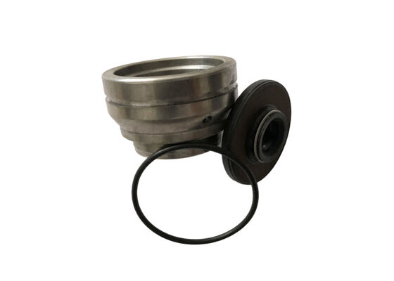
A shock absorber guide assembly is a multi-component unit used inside automotive and motorcycle hydraulic dampers. It consists of a powder metallurgy guide body, a piston rod oil seal, and a rubber sealing ring.
Unlike purchasing the guide body alone, this assembly combines the rod-guiding structure with the sealing components in one coordinated unit. The guide body provides structural support and mounting interfaces, the oil seal provides dynamic sealing around the reciprocating piston rod, and the rubber sealing ring provides sealing at the specified assembly interface.
Dimensional compatibility, seal positioning, and the fit between individual components are important when evaluating the complete assembly. Product development therefore involves more than checking the guide bore, outside diameter, and body thickness. Oil seal dimensions, lip configuration, and rubber ring cross-section and groove requirements must also be considered.
XIAYI supplies shock absorber guide assemblies with oil seals and rubber sealing rings. Configurations can be evaluated according to customer drawings, samples, and damper assembly requirements, providing coordinated component supply for automotive and motorcycle shock absorber manufacturers.
The guide body is manufactured using an iron-based powder metallurgy material system. It forms the main structural part of the assembly and provides mounting and mating interfaces for the piston rod and sealing components.
Material grade, density, hardness, bore dimensions, outside diameter, and any required secondary operations can be reviewed according to the product specification.
The assembly includes a shock absorber oil seal for dynamic sealing around the reciprocating piston rod.
Depending on the selected design, the oil seal can feature a main sealing lip and a dust lip.
The main lip forms the dynamic sealing interface with the piston rod to help retain hydraulic oil inside the damper. The dust lip helps limit the entry of external dust and contaminants into the sealing area.
NBR (nitrile rubber) and FKM (fluoroelastomer) are available as oil seal material options. Final selection should be based on damping oil compatibility, operating temperature, and the service medium.
A rubber sealing ring is included for sealing at the specified assembly interface.
In designs using an outer circumferential groove, the rubber ring may provide static sealing between the guide body and the damper housing. Its exact location, cross-sectional shape, and compression fit must be confirmed against the assembly drawing.
The rubber ring material, inner diameter, cross-section, and installation requirements should match the actual groove geometry and operating conditions. Visual similarity or nominal dimensions alone are not sufficient for replacement selection.
The guide body, oil seal, and rubber sealing ring perform different structural and sealing functions.
Supplying them as a coordinated assembly allows the component models, dimensions, and installation relationships to be reviewed together during sourcing.
For OEM projects, XIAYI can evaluate the assembly based on customer drawings and confirm the specifications and mating requirements of the individual components, helping reduce the risk of dimensional or model mismatches during separate purchasing.
The following data are taken from existing guide and oil seal product information. Parameters are listed separately for each component and are not universal specifications for every assembly model.
| Component | Parameter | Reference Specification | Technical Notes |
| Guide Body | Material | MPIF FC-0205 | Iron-based powder metallurgy |
| Guide Body | Density | 6.2–6.8 g/cm³ | Existing FC-0205 product specification |
| Guide Body | Hardness | HRB 65–90 | Existing product reference range |
| Guide Body | Surface treatment | Optional steam treatment | Depending on model and application |
| Guide Body | Steam treatment time | 2 hours | Reference process information |
| Guide Body | Fe₃O₄ oxide layer thickness | 0.004–0.005 mm | Reference value for steam-treated components |
| Oil Seal | Material options | NBR / FKM | Selected according to oil and temperature requirements |
| Oil Seal | Reference temperature range | -40°C to +120°C | Listed in existing oil seal information; confirm for selected material and model |
| Oil Seal | Sealing configuration | Main sealing lip + dust lip | Confirm according to the selected model |
| Oil Seal | Width tolerance | ±0.1 mm | Based on existing oil seal specifications |
| Oil Seal | Height tolerance | ±0.3 mm | Based on existing oil seal specifications |
| Rubber Sealing Ring | Material | To be confirmed by project | No universal material grade specified |
| Rubber Sealing Ring | Inner diameter and cross-section | According to drawing, in mm | Matched to the installation groove |
| Rubber Sealing Ring | Hardness | According to material specification, Shore A | Confirmed according to seal design and operating conditions |
| Complete Assembly | Outside diameter, bore, and total height | According to assembly drawing, in mm | Based on installation dimensions and customer drawings |
| Complete Assembly | Applications | Automotive and motorcycle shock absorbers | Confirm compatibility with the damper design |
Specification notes:
For a guide assembly containing multiple structural and sealing components, quality confirmation should cover both individual parts and the assembled unit.
| Inspection Item | Inspection Content | Main Quality Consideration |
| Guide Dimensions | Bore, outside diameter, thickness, and specified mating dimensions | Fit with piston rod and damper housing |
| Guide Material | Density, hardness, and material specification | Compliance with the approved material requirements |
| Oil Seal Dimensions | Overall dimensions, width, and height | Compatibility with the guide installation seat |
| Oil Seal Appearance | Sealing lips and surface condition | No visible damage, cuts, or abnormalities |
| Rubber Sealing Ring | Inner diameter, cross-section, and appearance | Compatibility with groove and compression requirements |
| Assembly Condition | Oil seal and rubber ring positioning | Avoid incorrect installation, twisting, or assembly damage |
| Complete Assembly | Critical dimensions and agreed sealing tests | According to customer acceptance criteria |
For projects with defined sealing performance requirements, static and dynamic sealing test procedures can be established based on customer specifications. Test pressure, test medium, duration, and leakage acceptance criteria should be clearly defined.
| Application | Assembly Requirements |
| Automotive Hydraulic Shock Absorbers | Guide body, piston rod oil seal, and housing interface sealing |
| Motorcycle Front Forks | Compact assembly dimensions and oil seal/rubber ring compatibility |
| Motorcycle Rear Shock Absorbers | Assembly specifications matched to piston rod and housing design |
| Monotube Shock Absorbers | Configuration confirmed according to internal reservoir and sealing interfaces |
| Twin-Tube Shock Absorbers | Assembly confirmed according to guide position and sealing design |
| OEM Shock Absorber Production | Drawing-based component assembly and inspection requirements |
To confirm the assembly specification and manufacturing approach, please provide:
XIAYI can review the compatibility of the guide body, oil seal, and rubber sealing ring against the assembly drawing, then confirm the material, dimensional, and installation requirements for OEM shock absorber guide assembly projects.
Q1: What components are included in the shock absorber guide assembly?
The assembly consists of a powder metallurgy guide body, a piston rod oil seal, and a rubber sealing ring. Exact component positions and configurations are defined by the relevant assembly drawing.
Q2: What is the difference between the oil seal and the rubber sealing ring?
The oil seal provides dynamic sealing around the reciprocating piston rod. The rubber sealing ring is generally used for static sealing at a specified assembly interface. Their positions, dimensions, and working conditions are different, so they should not be treated as interchangeable components.
Q3: Can the oil seal be supplied in NBR or FKM?
NBR and FKM are available material options in the existing oil seal product range. The final selection should consider damping oil compatibility, operating temperature, and the service medium.
Q4: Can the rubber sealing ring be customized according to customer drawings?
The material, inner diameter, cross-section, and installation requirements can be reviewed against customer drawings. For non-standard designs, please provide the sealing groove dimensions and complete assembly drawing.
Q5: Can the complete assembly be purchased instead of sourcing three components separately?
The complete assembly supply can be evaluated according to the project requirements. Before ordering, confirm the assembly drawing, individual component specifications, and acceptance criteria.
| MOQ: | 1000pcs |
| Price: | negotiation |
| Standard Packaging: | Standard exporting package |
| Delivery Period: | 30 working days for new samples |
| Payment Method: | T/T |
| Supply Capacity: | 50,000pcs per month |
A shock absorber guide assembly is a multi-component unit used inside automotive and motorcycle hydraulic dampers. It consists of a powder metallurgy guide body, a piston rod oil seal, and a rubber sealing ring.
Unlike purchasing the guide body alone, this assembly combines the rod-guiding structure with the sealing components in one coordinated unit. The guide body provides structural support and mounting interfaces, the oil seal provides dynamic sealing around the reciprocating piston rod, and the rubber sealing ring provides sealing at the specified assembly interface.
Dimensional compatibility, seal positioning, and the fit between individual components are important when evaluating the complete assembly. Product development therefore involves more than checking the guide bore, outside diameter, and body thickness. Oil seal dimensions, lip configuration, and rubber ring cross-section and groove requirements must also be considered.
XIAYI supplies shock absorber guide assemblies with oil seals and rubber sealing rings. Configurations can be evaluated according to customer drawings, samples, and damper assembly requirements, providing coordinated component supply for automotive and motorcycle shock absorber manufacturers.
The guide body is manufactured using an iron-based powder metallurgy material system. It forms the main structural part of the assembly and provides mounting and mating interfaces for the piston rod and sealing components.
Material grade, density, hardness, bore dimensions, outside diameter, and any required secondary operations can be reviewed according to the product specification.
The assembly includes a shock absorber oil seal for dynamic sealing around the reciprocating piston rod.
Depending on the selected design, the oil seal can feature a main sealing lip and a dust lip.
The main lip forms the dynamic sealing interface with the piston rod to help retain hydraulic oil inside the damper. The dust lip helps limit the entry of external dust and contaminants into the sealing area.
NBR (nitrile rubber) and FKM (fluoroelastomer) are available as oil seal material options. Final selection should be based on damping oil compatibility, operating temperature, and the service medium.
A rubber sealing ring is included for sealing at the specified assembly interface.
In designs using an outer circumferential groove, the rubber ring may provide static sealing between the guide body and the damper housing. Its exact location, cross-sectional shape, and compression fit must be confirmed against the assembly drawing.
The rubber ring material, inner diameter, cross-section, and installation requirements should match the actual groove geometry and operating conditions. Visual similarity or nominal dimensions alone are not sufficient for replacement selection.
The guide body, oil seal, and rubber sealing ring perform different structural and sealing functions.
Supplying them as a coordinated assembly allows the component models, dimensions, and installation relationships to be reviewed together during sourcing.
For OEM projects, XIAYI can evaluate the assembly based on customer drawings and confirm the specifications and mating requirements of the individual components, helping reduce the risk of dimensional or model mismatches during separate purchasing.
The following data are taken from existing guide and oil seal product information. Parameters are listed separately for each component and are not universal specifications for every assembly model.
| Component | Parameter | Reference Specification | Technical Notes |
| Guide Body | Material | MPIF FC-0205 | Iron-based powder metallurgy |
| Guide Body | Density | 6.2–6.8 g/cm³ | Existing FC-0205 product specification |
| Guide Body | Hardness | HRB 65–90 | Existing product reference range |
| Guide Body | Surface treatment | Optional steam treatment | Depending on model and application |
| Guide Body | Steam treatment time | 2 hours | Reference process information |
| Guide Body | Fe₃O₄ oxide layer thickness | 0.004–0.005 mm | Reference value for steam-treated components |
| Oil Seal | Material options | NBR / FKM | Selected according to oil and temperature requirements |
| Oil Seal | Reference temperature range | -40°C to +120°C | Listed in existing oil seal information; confirm for selected material and model |
| Oil Seal | Sealing configuration | Main sealing lip + dust lip | Confirm according to the selected model |
| Oil Seal | Width tolerance | ±0.1 mm | Based on existing oil seal specifications |
| Oil Seal | Height tolerance | ±0.3 mm | Based on existing oil seal specifications |
| Rubber Sealing Ring | Material | To be confirmed by project | No universal material grade specified |
| Rubber Sealing Ring | Inner diameter and cross-section | According to drawing, in mm | Matched to the installation groove |
| Rubber Sealing Ring | Hardness | According to material specification, Shore A | Confirmed according to seal design and operating conditions |
| Complete Assembly | Outside diameter, bore, and total height | According to assembly drawing, in mm | Based on installation dimensions and customer drawings |
| Complete Assembly | Applications | Automotive and motorcycle shock absorbers | Confirm compatibility with the damper design |
Specification notes:
For a guide assembly containing multiple structural and sealing components, quality confirmation should cover both individual parts and the assembled unit.
| Inspection Item | Inspection Content | Main Quality Consideration |
| Guide Dimensions | Bore, outside diameter, thickness, and specified mating dimensions | Fit with piston rod and damper housing |
| Guide Material | Density, hardness, and material specification | Compliance with the approved material requirements |
| Oil Seal Dimensions | Overall dimensions, width, and height | Compatibility with the guide installation seat |
| Oil Seal Appearance | Sealing lips and surface condition | No visible damage, cuts, or abnormalities |
| Rubber Sealing Ring | Inner diameter, cross-section, and appearance | Compatibility with groove and compression requirements |
| Assembly Condition | Oil seal and rubber ring positioning | Avoid incorrect installation, twisting, or assembly damage |
| Complete Assembly | Critical dimensions and agreed sealing tests | According to customer acceptance criteria |
For projects with defined sealing performance requirements, static and dynamic sealing test procedures can be established based on customer specifications. Test pressure, test medium, duration, and leakage acceptance criteria should be clearly defined.
| Application | Assembly Requirements |
| Automotive Hydraulic Shock Absorbers | Guide body, piston rod oil seal, and housing interface sealing |
| Motorcycle Front Forks | Compact assembly dimensions and oil seal/rubber ring compatibility |
| Motorcycle Rear Shock Absorbers | Assembly specifications matched to piston rod and housing design |
| Monotube Shock Absorbers | Configuration confirmed according to internal reservoir and sealing interfaces |
| Twin-Tube Shock Absorbers | Assembly confirmed according to guide position and sealing design |
| OEM Shock Absorber Production | Drawing-based component assembly and inspection requirements |
To confirm the assembly specification and manufacturing approach, please provide:
XIAYI can review the compatibility of the guide body, oil seal, and rubber sealing ring against the assembly drawing, then confirm the material, dimensional, and installation requirements for OEM shock absorber guide assembly projects.
Q1: What components are included in the shock absorber guide assembly?
The assembly consists of a powder metallurgy guide body, a piston rod oil seal, and a rubber sealing ring. Exact component positions and configurations are defined by the relevant assembly drawing.
Q2: What is the difference between the oil seal and the rubber sealing ring?
The oil seal provides dynamic sealing around the reciprocating piston rod. The rubber sealing ring is generally used for static sealing at a specified assembly interface. Their positions, dimensions, and working conditions are different, so they should not be treated as interchangeable components.
Q3: Can the oil seal be supplied in NBR or FKM?
NBR and FKM are available material options in the existing oil seal product range. The final selection should consider damping oil compatibility, operating temperature, and the service medium.
Q4: Can the rubber sealing ring be customized according to customer drawings?
The material, inner diameter, cross-section, and installation requirements can be reviewed against customer drawings. For non-standard designs, please provide the sealing groove dimensions and complete assembly drawing.
Q5: Can the complete assembly be purchased instead of sourcing three components separately?
The complete assembly supply can be evaluated according to the project requirements. Before ordering, confirm the assembly drawing, individual component specifications, and acceptance criteria.